Unbraced Lengths
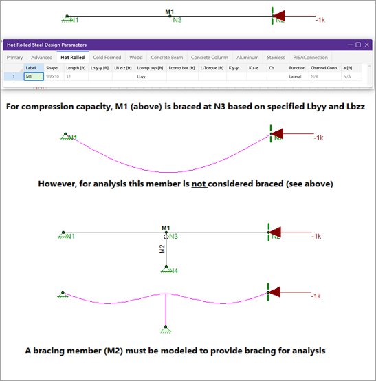
The member capacity for axial compression and for flexure is dependent on the spacing of elements which provide bracing along the length of a member. By default the program assumes that no bracing is provided along the length of the Physical Member. This is represented by the condition where the unbraced length field is shown as empty/blank.
You may specify unbraced lengths as a fixed distance or by using RISA's Unbraced Length Commands. The unbraced lengths are:
- Lbyy
- Lbzz
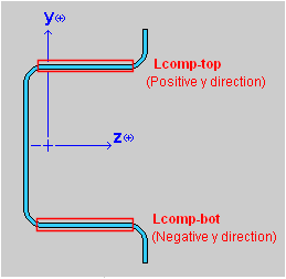
- Lcomp-top
- Lcomp-bot
- L-torque
The unbraced lengths that are used for member capacity calculations are listed in the Member Detail report after solution.
Lb Values (Lb, Lu, Le)
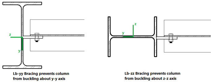
The Lb values: Lbyy andLbzz,represent the distance between points which brace the member against Flexural (column-type) Buckling about the member's local y and z axes, respectively. Lb bracing prevents the entire member from moving laterally (perpendicular to its own axis). These Lb values are used to calculate slenderness ratios (KL/r) for both directions, which are used in the calculation of member axial compression capacity.
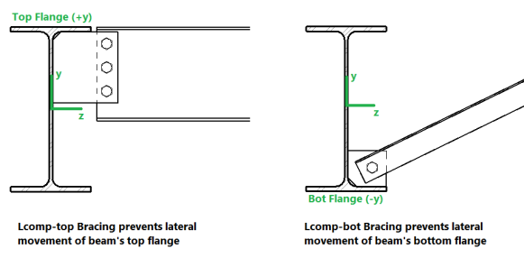
Lcomp Values (Lcomp, Le-bend)
The Lcomp values, Lcomp-top and Lcomp-bot, represent the distance between points which brace the top or bottom flange of the member against Lateral-Torsional (beam-type) Buckling. These Lcomp values are used to calculate the member's flexural (bending) capacity. Where the top flange of the member is in compression due to bending, Lcomp-top is used. Where the bottom flange of the member is in compression due to bending, Lcomp-bot is used. Lcomp bracing prevents the member's flange from moving laterally (perpendicular to the member's axis).
Members which experience a moment reversal along their length (such as fixed-end or continuous members) have compression in both the top and bottom flange (although not simultaneously). The program uses the appropriate Lcomp (top or bottom) based on moment direction to calculate the bending capacity at each internal section along the member.
The top flange is the flange on the positive local y-axis side of the member. Therefore if a beam if rotated 180 degrees about its own axis (flipped upside down) the "top" flange will actually be facing downwards.
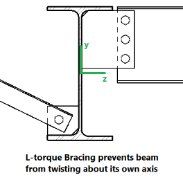
L-torque
The L-torque value represents the distance between points which restrain the member against twisting about its own axis. This value is used to calculate the member's Torsional Buckling and Flexural-Torsional Buckling capacity. These limit states affect the member's axial compression capacity.
- The L-torque value is NOT used for calculations of stiffness or stress for members subjected to warping. This is done using an internal "warping length" set by the program.
- Not all design codes check for Torsional Buckling or Flexural-Torsional Buckling. For those that do, these limit states will only be checked if L-torque > LbzzandLbyy.
- Currently the AISC 360 code, CSA S16-14 code, Aluminum codes, and the 2010 and newer Cold Formed Steel codes support this unbraced length.
Automated Unbraced Length Commands
Aside from leaving the unbraced length blank or inputting a fixed distance, you can harness the program's ability to use a limited intelligence for determining unbraced lengths. In order to do this you can simply type in the name of the Unbraced Length Commands into the unbraced length field. If a valid command word is used then the program will accept and display that command in lieu of a distance value.
![]()
Some member types are pre-populated with an Unbraced Length Command when they are created. Below is a list of the commands which may be used:
Segment
When this command is used, all
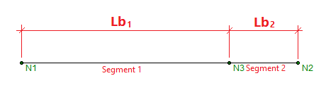
When using the Segment command the program will assume that each node along the length of the member can act as a brace location regardless of whether any bracing or restraint exists. In the example above this will result in an unconservative member capacity if no bracing will be supplied at N3 in real life.
Lbyy
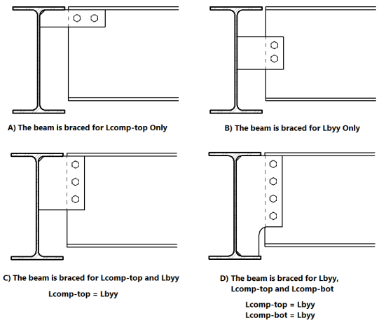
This command is only available for Lcomp-top and Lcomp-bot. When this command is used, the value entered for

Click on image to enlarge it
In the example below, Case C, the Lbyy command could be appropriately be used in the Lcomp-top field. In the example below, Case D, the Lbyy command could be appropriately used in both Lcomp fields. It would not be appropriate to use the Lbyy command for Case A or Case B below.
Floor
For RISA-3D models which are linked to RISAFloor models, if an unbraced length is set in RISAFloor, it is listed as Floor in RISA-3D spreadsheets. This indicates that the unbraced length was set in RISAFloor for all locations along the length of the member, and those same values are being used in the RISA-3D model.
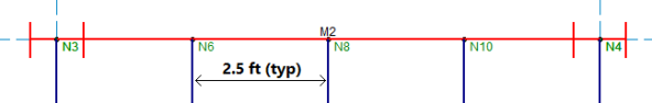
In the example below, the fixed-end beam M2 is using the Framing command for Lcomp-bot in RISAFloor.
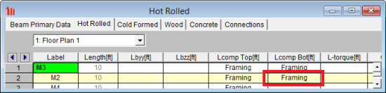
When this beam is brought into RISA-3D, the RISA-3D member properties show that Lcomp-bot is referencing RISAFloor (Floor).
After the model is solved you can confirm in the Member Detail Report that the RISAFloor unbraced length is being used. The maximum code check occurs at 0 feet from the i-end of the member. Because this is a fixed-fixed beam, the bottom flange is in compression there so Lcomp-bot is used instead of Lcomp-top.
Material Specific Behavior
Hot Rolled Steel
- For AISC ASD 9th Edition calculation of Kl/r for WTs and Double Angles, there is an effective Kl/r ratio that may be used when Flexural-Torsional buckling controls. This can be found in the commentary Section E3.
- Specifying LcompTop and LcompBot both as zero constrains a single angle to bend/buckle about its geometric axes. Otherwise it will behave about its principal axes.
- For single angles behaving about their principal axes, Lbyy specifies bracing against buckling about the minor principal axis. Lbzz specifies bracing against buckling about the major principal axis. See Member Results for more information on Single Angle behavior.
Cold Formed Steel
In general, the unbraced lengths for Cold Formed bending checks are based on the Lcomp value and axial checks are based on Lb values. Below describes more specifics based on the AISI 2012 code.
Lateral Torsional Buckling (AISI C3.1.2)
Lt = Lcomp
Lcomp is the unbraced length for the flange that’s in bending compression at that section (either Lcomp_top or Lcomp_bot).
This applies to all shapes and all AISI codes.
Lt= smaller of Lbyy and Lcomp
When Lateral Torsional Buckling governs over local buckling, the display of the Seff in the Detail Report will report the Sc which is the elastic section modulus of effective section calculate relative to the extreme compression fiber at Fc.
Distortional Buckling (AISI C3.1.4)
Lm=Lcomp
Lcomp is the unbraced length for the flange that’s in bending compression at that section (either Lcomp_top or Lcomp_bot).
Axial Strength (AISI C4.1)
L= Could be Lbyy or Lbzz, whichever gives the larger of (KL/r)yy or (KL/r)zz
Flexural Torsional Buckling or Torsional Buckling (AISI C4.1.2)
Lt= L-Torque
Lt= smaller of Lbyy and Lcomp
Distortional Buckling (AISI C4.2)
Lm= L-Torque
-
The Torsional Warping constant for Back-to-Back Channels and Tracks, Cw is calculated per the AISI prescribed doubly symmetric shapes (AISI-08 Manual 3.3.3) that are continuously welded (all the unbraced lengths are 0). If the Back-to-Back shape is not continuously welded (any of the unbraced lengths larger than zero), Cw is twice the value of each individual section.
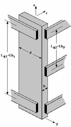
- For Hat Channel (HU) shape types, the Lcomp-top and Lcomp-bot values only apply to the flanges perpendicular to the local y axis (see image below). Therefore, if your loading is applied in the local z direction, these entries will not apply. This assumption was made in reference to section C3.1.2.1 of the AISI Specification with Commentary whose footnote tells us that the limit state of Lateral-Torsional Buckling does not apply to these shapes.
Concrete
- The unbraced lengths for Flexural Buckling (
- The unbraced lengths are used for the Moment Magnification procedure in older versions of the ACI code.
Wood
- The unbraced lengths for Flexural Buckling (
- The unbraced lengths for Lateral-Torsional buckling (Lcomp-top, Lcomp-bot) are called Le-bend Top and Le-bend Bot for wood. Their behavior is the same as the behavior for Lcomp-top and Lcomp-bot.
- See AF&PA NDS-2012, Table 3.3.3 for information on how to determine Le-bend based on the unbraced length. This procedure is not followed automatically in RISA.
Aluminum
- Specifying LcompTop and LcompBot both as zero constrains a single angle to bend/buckle about its geometric axes. Otherwise it will behave about its principal axes.
- For single angles behaving about their principal axes, Lbyy specifies bracing against buckling about the minor principal axis. Lbzz specifies bracing against buckling about the major principal axis. See Member Results for more information on Single Angle behavior.
For additional advice on this topic, please see the RISA Tips & Tricks webpage at risa.com/post/support. Type in Search keywords: Unbraced Lengths.
K Factors (Effective Length Factors)
Effective Length Factors (K) are recommended or required for some design codes. The effective length factor allows you to adjust the unbraced length for Flexural Buckling as a simplified method of accounting for buckling effects. Kyy is a modifier factor for Lbyy. Kzz is a modifier factor for Lbzz.
If the K Factor field is left blank/empty then it is taken as 1.0, thereby not affecting the unbraced length.
If a value is entered for a K Factor, that value will be used for
K Approximation Feature
RISA-3D
is able to approximate the recommended K values for a member based on the member's
sway condition and end release configuration. The K-factor
approximation is based on AISC 360, Table C-A-7.1. To access this feature you must be in the Members spreadsheet, on the tab which shows the unbraced lengths. Click the
![]()
Click on image to enlarge it
The following table gives the values the program calculates for various conditions.
| Table Case | End Conditions | Sidesway? | K-Value |
|---|---|---|---|
|
(a) |
Fixed-Fixed |
No |
.65 |
|
(b) |
Fixed-Pinned |
No |
.80 |
|
(c) |
Fixed-Fixed |
Yes |
1.2 |
|
(d) |
Pinned-Pinned |
No |
1.0 |
|
(e) |
Fixed-Free |
Yes |
2.1 |
|
(f) |
Pinned-Fixed |
Yes |
2.0 |
RISA-3D recognizes a pinned boundary condition for the K approximation for a full pin, i.e. if all the rotations in the boundary condition are released. If any of the rotations in a boundary condition are restrained, the boundary condition is considered "fixed" for the K factor approximation.
Any configuration not described here is given the default value of '1.0'.
If any value that influences these K values is changed, the K factor approximation should be redone. For instance, if you have RISA-3D approximate K factors, then change some of the member end release designations, you should redo the K factor approximations.
Remember that the K factors are approximations and you should check to make sure you agree with all K factors RISA-3D assigns. You can always override a K factor after an approximation by directly entering the value that you want in the appropriate field. Keep in mind that a subsequent approximation will overwrite any manually input values so you will need to override the approximation each time it is performed.

Click on image to enlarge it
Limitation:
RISA-3D will currently neglect the influence of adjoining framing members when those members are connected at a joint that also has degrees of freedom restrained by boundary conditions. For example, suppose a column and beam member connect at a joint that is restrained for translation in all directions (i.e. the joint is "pinned"). The K factor approximation will neglect the beam member when it calculates the K factor for the column and visa-versa. The effect will be that the ends of the members at that joint will be seen as "pinned" and not "fixed" for the K factor approximation.
Sway Flags
The Sway Flags indicate whether the member is to be considered subject to sidesway for bending about its local y and z axes. The y sway field is for y-y axis bending and the z sway field is for z-z axis bending. Click on the field to check the box and indicate that the member is subject to sway for that particular direction, or leave the entry blank if the member is braced against sway. These sway flags influence the calculation of the K factors as well as the Cm and Cb factors.